Diode Forward and Reverse Bias on an Oscilloscope
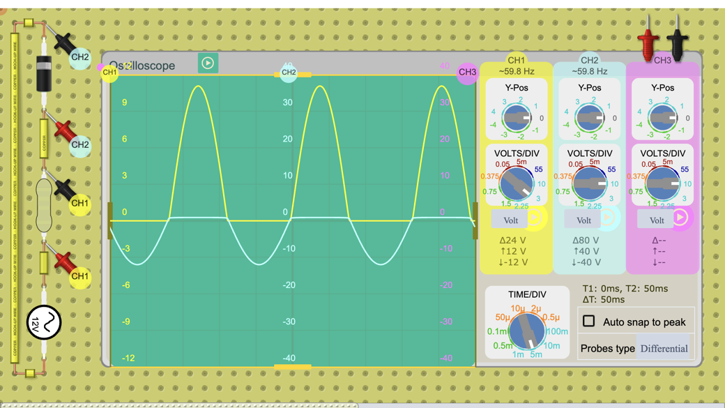
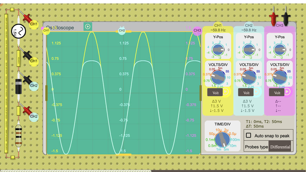
A 1.5 V, 60 Hz AC source drives a silicon diode and a 1 Ω resistor. The oscilloscope shows the source on channel 1 and the diode voltage on channel 2, so…
Use this circuit in class: Diode lab: forward bias, reverse bias and the I-V curve
Teaching with circuits?
Create a classroom, give your students a circuit to build, and review what they submit. Try it free with one classroom and up to 5 students.
Try the free classroom demoHow it works
On the positive half of each cycle the diode is forward biased: it conducts about 0.71 A at the peak while its voltage stays near 0.79 V. On the negative half it is reverse biased: the current drops to almost zero and the diode holds the whole −1.5 V.
Flip the diode to make it conduct on the other half of the cycle, or change the source voltage to trace the diode's current-voltage curve.
What's inside
- 1× Power Source
- 1× Resistor (998 mΩ)
- 1× Diode
- Measured with Oscilloscope