D flip Flop (Hold/Set/Reset)
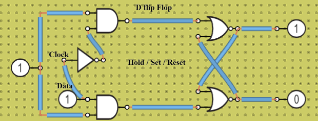
Input: Clock = 0, Data = 0 (HOLD) Steering Gates: The Clock (0) is connected to one input of both the top and bottom AND gates. Since an AND gate requires…
Teaching with circuits?
Create a classroom, give your students a circuit to build, and review what they submit.
See classroom plansHow it works
Input: Clock = 0, Data = 0 (HOLD)
Steering Gates: The Clock (0) is connected to one input of both the top and bottom AND gates. Since an AND gate requires all inputs to be 1 to output a 1, both AND gates are forced to output 0.
Latch Gates: The cross-coupled NOR gates receive 0 and 0 from the AND gates. In a NOR-based latch, an input of (0, 0) does not change the outputs. The gates maintain whatever values they previously held.
Result: HOLD state. The outputs remain unchanged.
Input: Clock = 0, Data = 1 (HOLD)
Steering Gates: Even though Data is 1, the Clock is still 0. The 0 from the Clock keeps both the top and bottom AND gates disabled, forcing both of their outputs to stay at 0.
Latch Gates: Just like the previous state, the cross-coupled latch receives 0 and 0 at its inputs.
Result: HOLD state. The circuit completely ignores the Data change because the Clock is low, keeping the previous outputs.
Input: Clock = 1, Data = 0 (RESET)
Steering Gates: Data (0) goes through the NOT gate and turns into a 1, which enters the bottom input of the top AND gate. Since the Clock is also 1, the top AND gate outputs 1. Data (0) goes directly into the bottom AND gate. Since one input is 0, the bottom AND gate outputs 0.
Latch Gates: The top NOR gate receives a 1 from the top AND gate. Any 1 into a NOR gate forces its output to 0. Therefore, the Top Output becomes 0. This 0 travels down the cross-coupling wire into the bottom NOR gate. The bottom NOR gate now has two 0 inputs (0 from the bottom AND gate and 0 from the top output), which causes it to output a 1. Therefore, the Bottom Output becomes 1.
Result: RESET state (Top Output = 0, Bottom Output = 1).
What's inside
- 9× Logic Gate