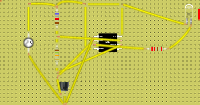
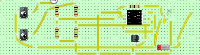
555 timer - Astable Mode - AC
The 555 Timer IC can be connected either in its Monostable mode thereby producing a precision timer of a fixed time duration, or in its Bistable mode to…
Teaching with circuits?
Create a classroom, give your students a circuit to build, and review what they submit.
See classroom plansHow it works
The 555 Timer IC can be connected either in its Monostable mode thereby producing a precision timer of a fixed time duration, or in its Bistable mode to produce a flip-flop type switching action. But we can also connect the 555 timer IC in an Astable mode to produce a very stable 555 Oscillator circuit for generating highly accurate free running waveforms whose output frequency can be adjusted by means of an externally connected RC tank circuit consisting of just two resistors and a capacitor.
The 555 Oscillator is another type of relaxation oscillator for generating stabilized square wave output waveforms of either a fixed frequency of up to 500kHz or of varying duty cycles from 50 to 100%. In the previous 555 Timer tutorial we saw that the Monostable circuit produces a single output one-shot pulse when triggered on trigger input.
Whereas the 555 monostable circuit stopped after a preset time waiting for the next trigger pulse to start over again, in order to get the 555 Oscillator to operate as an astable multivibrator it is necessary to continuously re-trigger the 555 IC after each and every timing cycle.
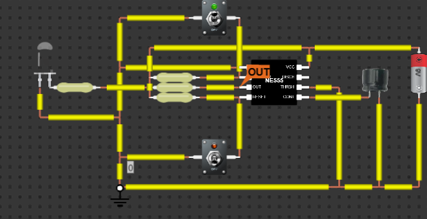
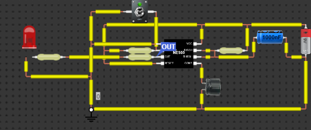
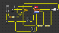
This re-triggering is basically achieved by connecting the trigger input the threshold input together, thereby allowing the device to act as an astable oscillator. Thus a 555 Oscillator has no stable states as it continuously switches from one state to the other. Also the single timing resistor of the previous monostable multivibrator circuit has been split into two separate resistors, R1 and R2 with their junction connected to the discharge input as shown below.
What's inside
- 1× Power Source
- 3× Resistor (10 kΩ, 48 kΩ)
- 2× Capacitor
- 1× LED
- 1× Integrated circuit