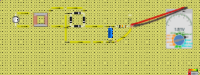
Full wave bridge rectifier
The Full Wave rectifier is the electronic circuit which converts the AC voltage into pulsating DC voltage. The diode is used to turn the negative half…

How it works
The Full Wave rectifier is the electronic circuit which converts the AC voltage into pulsating DC voltage.
The diode is used to turn the negative half cycle of the AC voltage into positive and the another positive half cycle of the AC voltage combined togather formes the pulse DC Voltage.
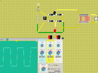
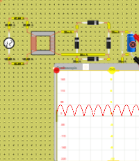
In the circuit the Bridge Rectifier is shown which has the step down transformer and a diode bridge in order to convert the high AC voltage into useable Low DC voltage.
What's inside
- 1× Power Source
- 1× Resistor (199 Ω)
- 1× Capacitor
- 1× LED
- 4× Diode
- 1× Transformer
- Measured with Oscilloscope